

Custom Contactor Design Essentials for Reliable Motor Control
2026-08-15
When a motor contactor fails, production stops—and standard off-the-shelf units often can't handle demanding loads or harsh environments. That's where custom design becomes essential. From coil voltage to contact materials, every choice affects long-term reliability in motor control. ETEK understands these nuances, offering tailored solutions that keep motors running smoothly. This guide breaks down the key design considerations you need for dependable performance.
Contact Material Pairings That Survive Frequent Motor Reversals
When a motor reverses direction under load, the contacts open and close against currents that can be six to eight times the full-load rating. The arc that forms across the separating surfaces isn't a single clean break; it's a series of re-strikes that erode material and push molten metal from one face to the other. Pairing a harder, arc-resistant material on the moving contact with a softer, oxidation-tolerant material on the stationary side often gives better life than using the same alloy on both. Silver tin oxide against silver nickel is a common start: the oxide dispersions in silver tin oxide resist welding and erosion, while the nickel content in the silver nickel side keeps contact resistance low after long idle periods.
Silver cadmium oxide paired with fine silver or silver copper still appears in older reversing contactors, and it works because the cadmium vapor quenches the arc and limits surface damage. But the cadmium-free alternatives have become more standard in new designs. Silver zinc oxide and silver tin oxide both develop a higher melting point than pure silver, so they don't transfer material as easily to the opposite face. Combining one of these with a silver graphite auxiliary arcing contact can handle the worst reversal duty, since the graphite burns away cleanly instead of welding the main contacts shut.
There's no universal pairing that wins in every reversing application. The correct choice depends on how often reversals happen, the voltage level, and whether the load is inductive or resistive. What matters is testing the actual pair under repeated reversing cycles and watching for uneven erosion and transfer. A pairing that survives on paper may fail because one contact grows a spike while the other wears a crater. Matching the materials' arc mobility and thermal conductivity to the reversal frequency keeps the damage distributed evenly, which is the practical goal.
Arc Chamber Geometry Shaped by Inrush and Plugging Loads
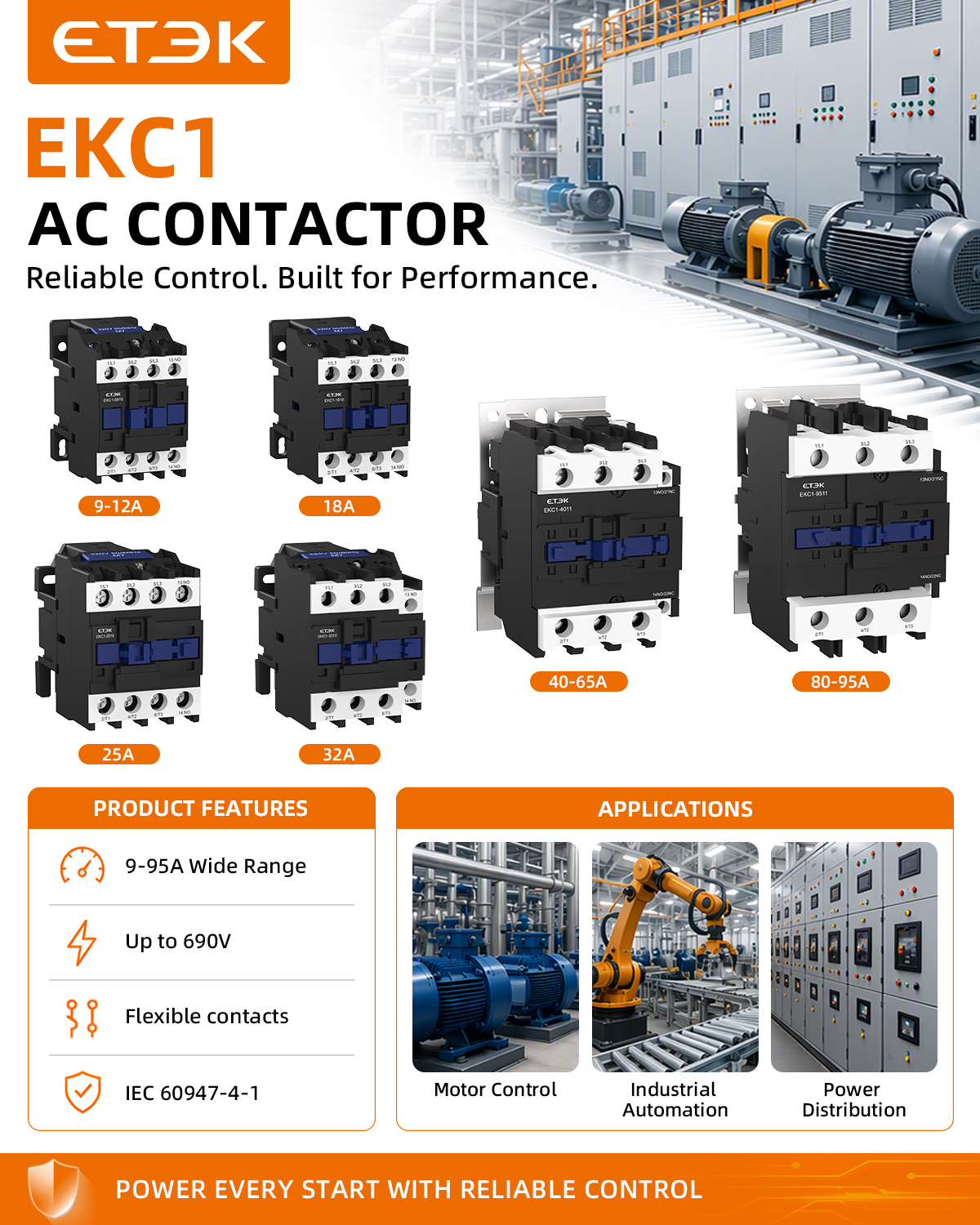
The geometry of an arc chamber rarely evolves from steady-state ratings alone. When a breaker or contactor faces transformer inrush currents—often ten to fifteen times nominal—or repeated plugging of live loads, the resulting arc is anything but symmetric. Early designs assumed a cylindrical chamber, but high-speed imaging shows that inrush arcs cling to the outer electrode edges, forcing a wider throat and steeper horn angles to keep the arc root moving before it welds material to the contact face.
Plugging loads, especially motor and capacitive banks, introduce a different pattern: the arc reignites after each zero crossing with violent re-strike energy. This pushes the chamber toward elongated side vents and a tapered crown, because the pressure wave from a re-strike can otherwise crack a uniform wall. A slightly flattened back wall, often no more than three to five degrees off vertical, redirects the plasma jet away from the arc splitter stack, directly shaping the internal ribs you see in modern MCCB molds.
What separates a durable arc chamber from an also-ran is how the geometry handles the mixed regime—high inrush peaks followed by plugging restrikes. Narrowing the arc channel near the splitter plates improves cooling but raises peak pressure during plugging events, so designers typically add a curved bypass notch below the runner. This seemingly minor cut lets the hot gas expand laterally without short-circuiting the arc path, a subtle trade-off that only shows up after hundreds of plugging cycles on a test bench.
Coil Magnetic Circuits Tuned for Low-Voltage Ride-Through
Adjusting the magnetic circuit of a coil is rarely the first thing engineers reach for when tackling low-voltage ride-through, yet it can quietly reshape how a system behaves during a sag. By deliberately introducing a small air gap or reshaping the core geometry, the coil's inductance becomes less sensitive to sudden current spikes. This subtle change means the magnetic flux does not saturate as violently when grid voltage dips, keeping the reactive power exchange more predictable and less likely to trip protective relays.
Tuning the magnetic path also alters the time constant of the coil, which directly affects how quickly stored energy can be released back into the circuit. Instead of relying solely on external crowbars or DC-link choppers, a well-tuned coil can absorb part of the transient on its own. For example, using a distributed gap core made from low-loss powder material spreads the flux density more evenly, reducing hot spots and allowing the coil to ride through a few extra cycles without overheating. Field experience shows this approach works best for medium-voltage drives where space for extra protection hardware is tight.
The practical payoff shows up in reduced stress on the inverter semiconductors and fewer nuisance trips during remote grid faults. A coil tuned for low-voltage ride-through does not need exotic materials—often a re-evaluation of lamination thickness, gap placement, and winding distribution is enough. The key is to model the magnetic circuit not as a fixed inductance but as a controllable energy buffer that shifts its saturation knee just below the expected fault current level. This keeps the control loop stable and extends the ride-through window without adding significant cost.
Thermal Sinking Paths That Prevent Nuisance Trips During Stall
During a stall, motor windings face a sudden surge in current that rapidly drives up junction temperatures. Without a carefully engineered thermal sinking path, heat collects around the power stage and can push protection circuits into false trips—even though the actual fault condition may be brief and self-correcting. The key is to route heat away from sensitive sensing nodes before it crosses the threshold that triggers an unwanted shutdown.
A well-designed sinking path uses low-resistance thermal vias, direct copper pours under the switching devices, and strategic placement of temperature sensors away from hot spots. By adding thermal capacitance near the die and keeping the path to the heatsink as short as possible, the system absorbs short-duration stall energy without letting surface temperatures spike. This approach turns the PCB itself into a buffer, smoothing out thermal transients that would otherwise confuse the overcurrent logic.
The payoff is a drive that stays online through mechanical jams, heavy starting loads, or momentary rotor lockups. Engineers who focus on thermal sinking paths—rather than simply raising trip thresholds—preserve both motor health and uptime. It’s a subtle shift from reactive protection to proactive thermal management, and it eliminates the frustration of nuisance trips that bring production lines to an unnecessary halt.
Auxiliary Contact Configurations for Real-Time Load Feedback
Auxiliary contacts on contactors and circuit breakers serve as the eyes of an electrical system when it comes to load status. Rather than guessing whether a motor is actually running or a heater element has engaged, these small switch mechanisms deliver a binary signal the moment the main contacts change position. For real-time load feedback, the configuration of these contacts—normally open, normally closed, or a mix of both—determines how accurately and quickly a control system can react to changing conditions on the floor.
In practice, engineers often pair a normally open auxiliary contact with a programmable logic controller input to confirm that a contactor has closed and current is flowing to the load. When the contactor de-energizes, the same contact opens, dropping the feedback signal within milliseconds. Some designs add a normally closed contact wired to an alarm circuit, so that an unexpected dropout or welded main contact triggers an immediate warning. Choosing the right combination means thinking through every failure mode: a stuck-open auxiliary contact could report a false positive, while a welded main contact might keep the normally open signal high even after the coil is commanded off.
Beyond simple status reporting, advanced configurations route these auxiliary signals into energy management systems or motor protection relays. By monitoring the exact moment a load turns on and off, facilities can track duty cycles, detect abnormal operation patterns, and schedule preventive maintenance before a minor issue becomes a production halt. The key is not just adding auxiliary contacts for the sake of it—each one should serve a specific feedback purpose, whether that is interlocking a second contactor, signaling a human-machine interface, or feeding a data historian for long-term load analysis.
Sealing and Venting Balance for Dusty Motor Control Environments
Dust infiltrating a motor control enclosure does more than settle on components; it coats heat sinks, clogs air paths, and accelerates contact wear. A fully sealed cabinet might keep particles out, but it also traps the heat generated by drives and contactors, pushing internal temperatures past safe operating limits. The real challenge isn't choosing between sealing and ventilation—it's finding the point where both can coexist without sacrificing one for the other. This balance shifts with dust particle size, humidity, and whether the dust is conductive or abrasive, meaning a solution that works in a cement plant may fail in a grain processing facility.
One practical approach is to stop treating the enclosure as a single sealed box and instead manage pressure differentials. A controlled positive pressure system, using a small blower with a high-efficiency filter, keeps dust from entering through cable glands or door gaskets by maintaining internal air pressure slightly above ambient. The ventilation opening then becomes the filtered intake, while exhaust is deliberately limited to a small, protected outlet. This works well until the filter loads up; in heavy dust, a clogged intake can drop the internal pressure below ambient within hours, essentially turning the cabinet into a vacuum chamber that pulls dust through every microscopic gap. That's why monitoring differential pressure—not just temperature—becomes critical in these environments.
For intermittent dust exposure, a simpler hybrid often suffices: seal the enclosure to IP54 or better, then add a filtered fan that only runs when internal temperature exceeds a set point. During dusty periods, the fan stays off and the cabinet relies on natural convection through sealed, gasketed seams. During cleaner shifts or maintenance windows, the fan provides active cooling. The filter media choice matters as much as the sealing strategy—pleated synthetic filters with a hydrophobic coating resist moisture-laden dust better than standard foam, and they can be swapped without opening the main door. Ultimately, the balance isn't static; it requires understanding the dust load profile over time and designing the enclosure to tolerate both extremes without operator intervention.
FAQ
Different motor types produce different inrush and switching arcs. Silver tin oxide handles high inrush better than silver cadmium oxide in many AC-3 applications, while silver nickel works well for frequent DC switching. The contact geometry and material transfer characteristics have to match the actual duty cycle, not just the nameplate current.
You need to consider the worst-case voltage sag during motor startup, not just the nominal control voltage. A coil that drops out at 80% of nominal may still fail in plants with long control wiring or heavy load startup. Custom designs often include a wider pickup and dropout window, plus transient suppression to avoid coil overvoltage.
Motor loads can produce sustained arcs that erode contacts and generate heat. Custom designs often use arc chutes with rare earth magnets or specific venting geometries to stretch and cool the arc faster. The goal is to keep contact bounce and arc duration short enough that the contactor survives millions of operations.
The armature and contact carrier mass, spring preload, and gap geometry all affect bounce. A lighter moving assembly with a well-tuned return spring can close faster and with less rebound. Custom designs often adjust these parameters to match the specific motor horsepower and control voltage.
If space is tight or the motor has unusual thermal characteristics, integrating the overload relay allows the trip class to be tailored to the motor's locked rotor time. This avoids nuisance tripping on high inertia loads while still protecting against locked rotor conditions.
Many standard auxiliaries use wiping contacts that self-clean but can wear quickly if switching inductive loads. Custom designs may use bifurcated contacts for low current signals, or gold flash over silver for dry circuit reliability. The contact gap and overtravel can also be increased for longer mechanical life.
Vibration and shock are common hidden killers. A contactor mounted near a large motor or gearbox can experience micro-fretting on closed contacts and false openings. Custom designs may add shock-absorbing mounts, higher contact force, or latching mechanisms to handle these conditions without excessive size.
Life testing should replicate the actual operating frequency and load, not just a generic endurance run. Accelerated testing at higher temperatures can reveal spring relaxation and contact wear, but the acceleration factor must be verified for the specific materials. Field validation with a small pilot batch is usually still necessary.
Conclusion
In reversing motor applications, the contact material pairing dictates survival. Silver–tungsten or silver–molybdenum faces shrug off metal transfer and micro-welding caused by plugging and locked-rotor inrush. Arc chamber geometry must match this violence: deep splitter plates, angled runners, and a magnetic blowout field pull the arc away from contact crowns before it can erode a single spot. At the coil end, a carefully shaped magnetic circuit with a low-reluctance return path and a robust shading ring keeps the armature sealed during brownouts and momentary line dips, avoiding chatter that destroys contacts.
Thermal behavior under stall is often overlooked. Instead of relying on heater elements alone, designers create explicit heat-sinking routes from the moving contact bridge through copper braids and terminal lugs into the panel bus. This keeps the bimetal or electronic trip unit reading true motor current rather than local contact heating. Auxiliary contacts arranged for early-make and late-break give PLCs a clean status signal without external interposing relays. In dusty environments, a filtered labyrinth vent lets air expand and contract while blocking conductive dust, and gasketed terminal covers prevent arc byproducts from escaping into control cabinets. Together, these elements form a contactor that tolerates frequent reversals, sagging voltage, stall currents, and dirty air without nuisance dropouts.
Contact Us
Contact Person: Andy
Email: [email protected]
Tel/WhatsApp: +86 13356133008
Website: https://www.etek-china.com/