

How Large Capacity Centrifugal Compressors Work: Unveiling Their Operating Principle
2026-07-25
Have you ever wondered what powers the immense air demands of large-scale industrial operations? The answer often spins quietly at the heart of these systems: the large capacity centrifugal compressor. Unlike smaller reciprocating units, these machines leverage high-speed impellers and diffusers to convert velocity into pressure with remarkable efficiency. But how exactly does this dynamic principle translate into reliable, continuous airflow at massive scales? At Seize Air, we believe understanding the operating principle is key to optimizing performance and uptime. In this post, we’ll strip away the complexity and reveal the elegant engineering behind these industrial workhorses—and why they remain a cornerstone of modern compressed air systems.
Transforming Speed into Pressure: The Centrifugal Force Effect
In the world of fluid dynamics, there exists a brilliantly simple yet powerful principle: speed can be directly converted into pressure. This transformation is the heartbeat of the centrifugal force effect, where a rotating impeller flings fluid outward with increasing velocity. As the fluid accelerates, its kinetic energy surges, only to be smoothly converted into pressure energy the moment it encounters the volute casing or diffuser. It's an elegant dance of physics—velocity sacrificed at the altar of pressure, giving life to everything from household water pumps to massive industrial compressors.
The magic happens inside the pump housing. When the impeller spins, it imposes a centrifugal acceleration on every particle of the fluid, driving them radially outward. The faster the rotation, the greater the centrifugal force, and consequently, the higher the velocity imparted to the fluid. But velocity alone isn't the goal—it's the pressure that matters. As the fast-moving fluid leaves the impeller tips and enters a gradually expanding passage, its speed begins to drop. Thanks to Bernoulli's principle, this drop in velocity causes a rise in pressure. It's a seamless conversion that happens almost instantaneously, with no need for complex valving or reciprocating parts.
Engineers have long exploited this effect to design machines that move liquids and gases against formidable resistances. By carefully shaping the impeller blades and the surrounding casing, they can control exactly how much pressure rise occurs for a given rotational speed. The centrifugal effect doesn't just push fluid—it compresses it, stores energy within it, and delivers it on demand. Whether lifting water from a deep well or supercharging an engine, the process remains fundamentally the same: take speed, mold it with centrifugal force, and watch it emerge as steady, usable pressure.
Anatomy of a Giant: Impellers, Diffusers, and Volutes at Work
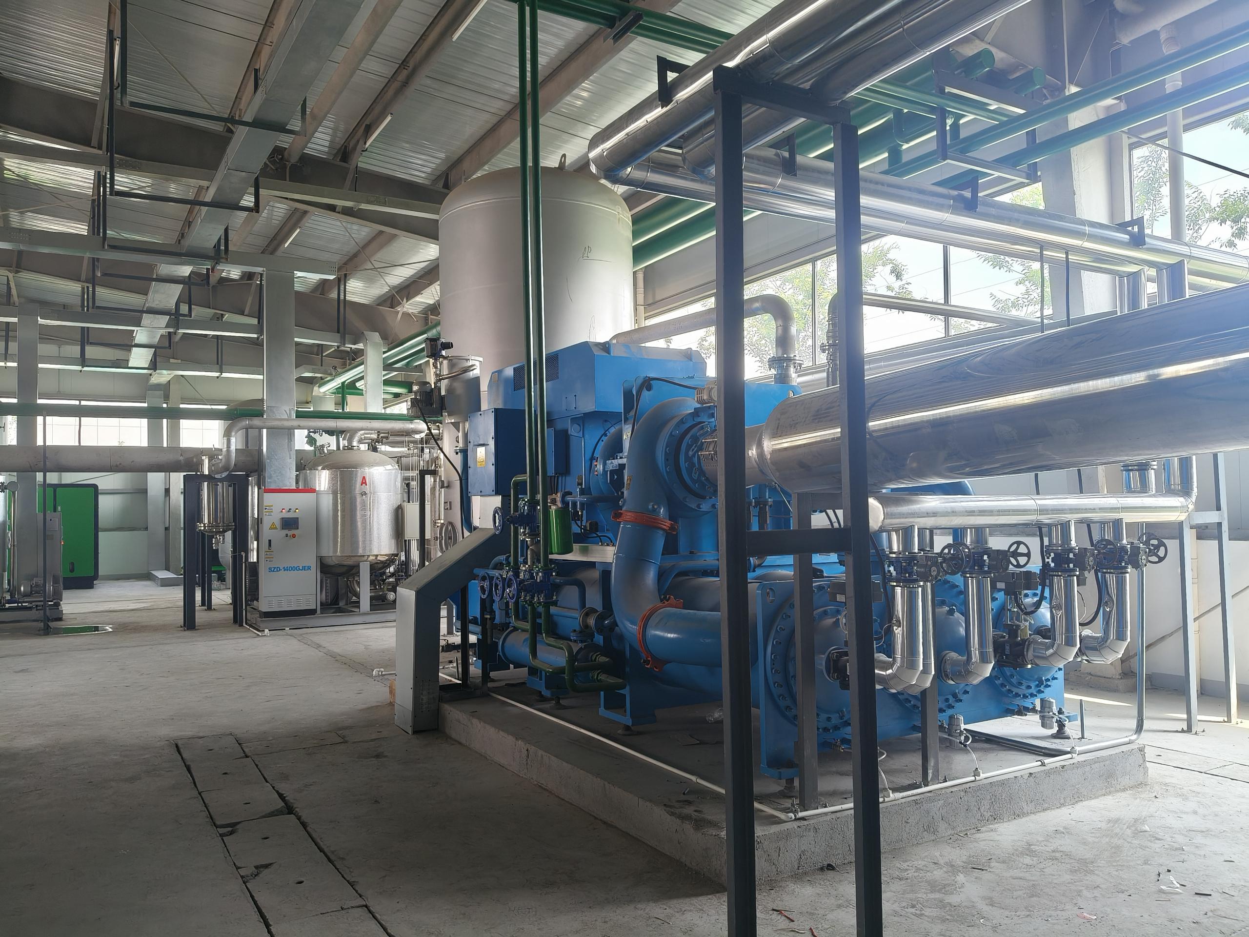
Peering inside a massive centrifugal pump, you quickly realize it’s not just a spinning disk—it’s a carefully choreographed dance of components. The impeller, rotating at tremendous speed, flings fluid outward with relentless centrifugal force. Its curved vanes grab the liquid and accelerate it, converting mechanical energy into kinetic energy in a split second. The shape and spacing of these vanes aren’t arbitrary; they’re sculpted to minimize turbulence and maximize flow, with every angle fine-tuned for a specific operating point.
As the fluid leaves the impeller’s eye and races toward the periphery, it meets the diffuser or volute, the unsung hero of pressure recovery. In a diffuser, a ring of stationary vanes gently decelerates the stream, transforming speed into stable pressure without chaotic eddies. A volute takes a different route: its spiral casing widens progressively, allowing the fluid to slow down and build pressure evenly around the impeller. This transition is delicate—too abrupt a deceleration and efficiency plummets, too gradual and the pump grows needlessly large.
What makes these giants truly remarkable is how they cope with real-world demands. The interplay between impeller and stationary components must handle varying loads without shaking itself apart or succumbing to cavitation. Engineers balance clearances, surface finishes, and material choices to cheat erosion and vibration. It’s a silent mechanical symphony: the impeller’s raw power, tamed and refined by diffusers and volutes, delivering fluid smoothly from intake to discharge, day after day, deep inside industrial heartbeats the world rarely sees.
The Gas Journey: From Suction to Compression in Milliseconds
Inside the compressor cylinder, the piston retreats, creating a sudden drop in pressure. The suction valve, a thin metal reed or ring, snaps open almost instantly. In a handful of milliseconds, low‑pressure refrigerant gas rushes in, drawn by the vacuum. There’s no pause, no hesitation—just a fluid, almost violent inhalation. The gas enters with a whisper of turbulence, curling into every corner of the chamber before the piston reaches bottom dead center and the valve slams shut.
Then comes the squeeze. As the piston reverses direction, the trapped gas has nowhere to go. The space collapses from inches to fractions of an inch, pressure building so fast it defies intuition. In less time than a camera flash, the refrigerant goes from a lazy vapor to a dense, superheated state. Eddy currents swirl, molecules slam together, and the temperature spikes—all hidden behind cast iron and steel. It’s a contained explosion without a flame, harnessed to do work.
By the time the discharge valve cracks open, the gas is already a different beast. Hot, compressed, and ready to release its borrowed energy, it bolts into the condenser at velocities that would shred lesser materials. The entire transformation—from suction to compression—unfolds in under 50 milliseconds on a typical 1,750 rpm machine. No wasted motion, no second chances. Just a silent, relentless rhythm that keeps the cycle alive.
Squeezing More with Less: The Secrets of Aerodynamic Efficiency
In the world of aerodynamics, efficiency isn't about brute force—it's about subtlety. The trick lies in manipulating airflow to minimize drag while generating just enough downforce or lift. Tiny adjustments, like a carefully placed vortex generator or a subtly reshaped mirror housing, can yield outsized gains. It’s a game of millimeters and milliseconds, where the difference between winning and losing is often invisible to the naked eye.
Consider the humble golf ball. Its dimples aren't decorative; they're a masterclass in drag reduction. By tripping the boundary layer into turbulence, they delay flow separation, shrinking the wake and cutting resistance. Automotive engineers borrow this principle with features like active grille shutters and underbody panels, which smooth the undercarriage airflow. In motorsport, diffusers and rear wings sculpt the air to claw back lost energy, turning chaotic wake into usable thrust.
The real secret, though, is holistic integration. The most efficient designs treat the entire vehicle as a single system, balancing every vent, crease, and spoiler. It's not about adding more parts, but about making every surface earn its keep. When a sedan’s trailing edge is tapered just so, or a truck’s cab roof is angled perfectly, the air works with the machine rather than against it. That's how you squeeze more speed and range from less energy—without shouting about it.
Scaling Up: Engineering Challenges for High-Capacity Operations
When you push a system to handle ten times its original capacity, the problems are rarely about adding more hardware. The real friction hides in the seams: data consistency across distributed nodes, thermal management that spirals beyond linear growth, and the sudden fragility of supply chains that once felt bulletproof. Every component works perfectly in isolation until load turns minor inefficiencies into cascading failures.
Redundancy models that shine at smaller scales start to betray you under heavy strain. A dual-power feed that promises 99.99% availability might become a single point of failure when both legs share a physical conduit you overlooked during expansion. Engineers learn to distrust their assumptions and start stress-testing not just systems, but the very blueprints they rely on. Architecture diagrams need a new layer: the hidden dependencies that only emerge when every buffer is exhausted at once.
The less glamorous side of scaling involves fighting battles in logistics and human coordination. Shipping delays for custom cooling parts cascade into site readiness schedules, while maintenance windows shrink as uptime targets tighten. Bridging the gap between theoretical capacity and operational reality demands a blend of creative workarounds and ruthless prioritization—because in high-capacity environments, the impossible just becomes the daily checklist.
Beyond the Basics: Where Mighty Compressors Drive Industry
Industrial compressors have long moved beyond simple tank filling and powering handheld tools. In heavy manufacturing, they become the silent pulse of entire production lines—feeding high-pressure air to massive stamping presses, controlling intricate robotic actuators, and even shaping molten materials through precisely metered gas flows. Without these workhorses, the seamless automation we take for granted would grind to a halt, revealing just how deeply they are woven into the fabric of modern factories.
Nowhere is their role more transformative than in petrochemical and energy sectors. Here, compressors don't just assist—they drive the core process. From cracking hydrocarbons under extreme pressures to circulating refrigerants in sub-zero liquefaction plants, their performance dictates throughput, efficiency, and safety. A single centrifugal compressor can weigh over 200 tons and spin at speeds that make metallurgy itself a limiting factor, pushing engineers to constantly rethink blade design and bearing technology just to keep these giants reliable 24/7.
What truly separates the ordinary from the extraordinary is how these machines adapt to niche demands. In food processing, oil-free screw compressors deliver contaminant-free air for packaging and fermentation, meeting strict health standards without sacrificing duty cycle. In desert mining operations, mobile diesel-driven units withstand scorching heat and choking dust while feeding drills that carve into the earth. Each environment shapes a unique breed of compressor, blending ruggedness with delicate control—proof that industrial air is far more than just a utility; it's a tailored force that reshapes what's possible.
FAQ
The impeller is driven by a prime mover, typically an electric motor or a steam turbine, connected through a shaft. In some cases, a gearbox is used to increase the rotational speed to the levels needed for effective compression.
It works by converting kinetic energy into pressure energy. The impeller spins at high speed, flinging gas outward and accelerating it. This high-velocity gas then enters a diffuser, where its speed is slowed, causing the kinetic energy to be transformed into increased static pressure.
Because a single stage can only achieve a limited pressure ratio. For high overall compression ratios, multiple impellers and diffusers are arranged in series. After each stage, the gas is typically cooled in an intercooler to reduce temperature and improve efficiency before entering the next stage.
Inlet guide vanes are adjustable blades at the compressor intake. They pre-whirl the gas entering the first impeller, allowing control over the flow rate and head, which improves part-load performance and overall efficiency across a wider operating range.
Tilting pad journal bearings and thrust bearings are commonly used to support the rotor and absorb axial forces. Dry gas seals or oil film seals are employed to prevent process gas from leaking along the shaft, and they must withstand high differential pressures while maintaining minimal friction and wear.
A horizontally split casing opens along a horizontal plane, making internal access easier for maintenance, and is used for lower to moderate pressures. A vertically split barrel compressor has a cylindrical body that slides into a casing, providing a more robust, leak-tight design for very high pressures or when handling hazardous gases.
Surge occurs at low flow rates when the compressor cannot sustain stable flow against the discharge pressure, causing violent flow reversals that can damage the machine. Choke, or stonewall, happens at very high flow rates when the gas velocity reaches sonic conditions, limiting throughput. Control systems use anti-surge valves and variable speed or guide vanes to keep operation away from these unstable zones.
Conclusion
Large capacity centrifugal compressors harness the principle of transforming kinetic energy into pressure head. At the core, the impeller accelerates gas radially outward, leveraging centrifugal force to dramatically increase velocity. The high-speed flow then enters a diffuser, where the conversion of velocity into static pressure occurs through carefully designed diverging passages. The volute subsequently collects the pressurized gas and directs it smoothly to the discharge. This entire gas journey—from suction to compression—happens in milliseconds, enabling continuous high-throughput operations. The intricate anatomy of impellers with their precision blades, coupled with optimally contoured diffusers and volutes, defines the compressor's performance envelope.
Achieving aerodynamic efficiency at such scales demands meticulous engineering. Modern designs incorporate computational fluid dynamics to minimize losses from shock waves, boundary layer separation, and secondary flows. Balancing rotor dynamics and managing axial thrust become formidable challenges when scaling up, requiring robust bearing systems and advanced sealing technologies. Beyond the machinery itself, these compressors are the heart of critical industrial processes: they drive large-scale air separation, natural gas liquefaction, and ethylene production. Their ability to handle massive gas volumes with minimal energy input makes them indispensable in sectors where reliability and efficiency are paramount. Continuous innovation in materials and cooling strategies pushes the capacity limits further, solidifying their role in sustainable industrial development.
Contact Us
Contact Person: Mia
Email: [email protected]
Tel/WhatsApp: +86 19821985894
Website: https://www.seize-air.com