

ODM PTFE Guidewire: Essential Considerations for Reliable Medical Device Manufacturing
2026-10-01
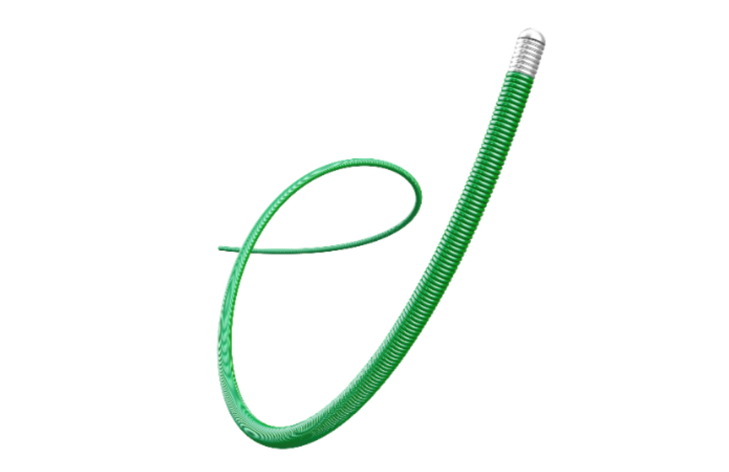
Selecting the right manufacturing partner for ODM PTFE guidewires can make or break your product's clinical success—yet too many teams overlook the subtle factors that separate reliable, high-performance devices from costly failures. From achieving consistent PTFE coating thickness to maintaining exceptional torque control and kink resistance, every detail matters in interventional procedures. At INT, we understand these challenges firsthand and have refined our processes to eliminate the guesswork, ensuring your guidewires meet rigorous regulatory standards while delivering the tactile precision physicians demand. In this article, we'll explore the critical considerations for ODM PTFE guidewire manufacturing, sharing insider insights that can help you avoid common pitfalls and accelerate your path to market with confidence.
PTFE Grade Selection Shapes Every Downstream Decision
PTFE grades are not a one-size-fits-all material choice, and the resin you pick before molding or machining sets the rules for every step that follows. A high-molecular-weight granular resin compresses into dense billets that hold dimensional stability during skiving, but the same grade may be too coarse for thin-walled paste-extruded tubing. Fine-cut powders flow differently in automatic presses and require different preform pressures; dispersions make sense for coating and impregnation but are impractical for solid stock shapes. If the grade doesn’t match the downstream process, you can expect porosity, internal stress, or uneven density that no amount of annealing will fully correct.
Filled PTFE grades amplify this effect. Adding glass fiber improves compressive strength and reduces cold flow, yet it turns machining into a tool-sharpening exercise and leaves a slightly abrasive surface on dynamic sealing lips. Bronze-filled PTFE pulls heat away from bearing contacts, but it can transfer color to mating parts and makes reliable adhesive bonding much harder. Carbon and graphite fillers improve wear life and lower friction, but they also shift thermal expansion enough that close-tolerance parts need re-dimensioning after a few temperature cycles. Each filler changes not just the material properties, but the entire sequence of cutting, deburring, cleaning, and assembly operations.
Even within virgin and modified PTFE, molecular weight and crystallinity control how much a part creeps under load or recovers after machining. A part cut from a low-crystallinity resin may relax overnight and lose the flatness it had on the lathe, while a highly crystalline grade holds its shape but can be more difficult to bond without chemical etching. That’s why experienced fabricators keep a short list of specific grades tied to each part geometry, tolerance band, and end-use environment. The grade selection is not a purchasing detail; it is the first downstream decision in the entire manufacturing route.
What Actually Happens When Coating Adhesion Fails
When a coating lets go, it rarely fails at the exact interface between paint and substrate. Instead, the break usually happens within a weak boundary layer just above or below that line. Contaminants like oils, salts, or even moisture trapped during application create a zone that can't hold stress. Over time, thermal cycling and moisture ingress work on that weak zone, causing blisters, flakes, or full delamination. You might notice the coating still looks intact in some places, but lift a corner and it peels away in sheets, leaving a clean, almost polished surface behind.
Adhesion loss isn't only a surface defect; it accelerates corrosion in ways that aren't immediately obvious. Once a coating separates from the metal, water and oxygen collect in the gap, forming a micro-environment that's often more aggressive than the outside exposure. The steel underneath starts to rust, but the coating can hide it until the damage is widespread. In industrial settings, this hidden corrosion under lifted coatings is a leading cause of structural weakening, because inspectors see only the painted surface and assume the protection is still there.
The failure also changes how the coating performs mechanically. A well-adhered film distributes stress across the entire surface, but a coating with poor adhesion concentrates stress at the edges of the detached area. This creates a peeling front that advances with each temperature swing or impact. Even small scratches become entry points for progressive delamination, because the coating can no longer share the load with the substrate. In the end, what starts as a tiny blister can strip an entire panel, leaving the base material exposed and vulnerable.
The Link Between Die Design and Guidewire Tip Feel
The way a guidewire tip transmits tactile information starts long before the wire reaches the patient. Die geometry dictates how the core wire tapers and how the outer coil or polymer jacket seats against it. A sharp transition inside the die produces an abrupt stiffness drop that reads as a vague, disconnected wiggle under fluoroscopy. In contrast, a gradual, multi-radius profile lets the tip load progressively, so the operator senses resistance building in a linear, predictable way.
Surface finish inside the die cavity often matters more than the drawing schedule itself. Microscopic chatter or uneven land lengths create localized cold-working that stiffens one side of the tip. That asymmetry translates into a guidewire that curves slightly off-axis when pushed against plaque or a vessel bifurcation. Polishing the die throat to a near-mirror finish and controlling the bearing length help maintain uniform wall thickness and roundness, which keeps the tactile feedback symmetric from every approach angle.
Tip feel also depends on how the die handles the final forming step, especially when a shaping ribbon or distal sleeve is involved. A die that squeezes the ribbon too tightly can flatten the distal few millimeters, making the wire feel dead and reluctant to recover after bending. Leaving just enough clearance for spring-back lets the tip store and release energy smoothly. That elastic response is what experienced operators describe as a "live" tip, one that communicates vessel contours without whipping or folding unexpectedly.
Why Sterilization Can Undo a Perfect PTFE Layer
PTFE layers look flawless after application, but sterilization isn't a passive rinse. Autoclave cycles push temperatures past 121°C while steam pressure flexes the substrate. PTFE expands at a different rate than the underlying metal or polymer, so each cycle creates shear stress at the interface. After enough cycles, you start seeing microscopic cracks that weren't there before—these become channels for moisture and contaminants, quietly undoing the barrier you worked so hard to build.
Radiation methods like gamma or e-beam are even less forgiving. High-energy photons snap carbon-fluorine bonds along the PTFE chain, leaving behind free radicals that recombine into shorter, weaker segments. The surface that once repelled everything now develops polar spots where proteins or process fluids can anchor. Ethylene oxide, while gentler on the polymer backbone, can still get trapped in newly formed micropores and later outgas, causing localized delamination. In short, sterilization doesn't just test the PTFE layer—it actively re-engineers its failure points.
Lot-to-Lot Consistency Starts With Resin Sourcing
A resin grade may carry the same datasheet name across suppliers, yet slight shifts in molecular weight distribution or additive loading can alter viscosity, crystallization speed, and even color stability downstream. These differences rarely show up in a routine melt flow test, but they accumulate into visible lot-to-lot drift once blending, molding, or extrusion starts.
Locking in a limited set of approved resin sources does more than stabilize pricing. It creates a controlled baseline: the catalyst system, chain-branching profile, and pellet handling stay within a known envelope. When a new lot arrives, the historical fingerprint from that supplier lets the QC team spot an outlier before it touches a production line, not after finished goods fail.
Consistency also depends on how the resin is sourced, stored, and moved. Moisture pickup in transport, regrind ratio at the supplier, and even seasonal changes in ambient humidity can shift processing behavior. Working with a supplier that shares batch-level production data, and keeping a small reference retention sample from each incoming lot, gives engineers a practical way to trace any variation back to its origin instead of adjusting machine settings blindly.
Design Transfer Pitfalls That Delay Regulatory Clearance
Regulators often flag design transfer gaps not because the device itself fails, but because the documentation trail breaks down. A classic trigger is when the production specifications drift from the verified design outputs—tolerances tighten or loosen without a formal change record. Reviewers then ask for re-validation data, and the clock resets. Another recurring issue is incomplete device master records that leave out critical manufacturing details like adhesive curing schedules or firmware load procedures, forcing regulators to issue deficiency letters simply to understand how the unit was actually built.
Process validation receives too little attention until the pre-submission audit surfaces missing IQ/OQ/PQ evidence for outsourced steps. Companies relying on a supplier's generic certificate without site-specific data often stall at this point. The same happens when test method transfers skip gage R&R studies, so the receiving lab can't demonstrate repeatability. Regulators then reject the design transfer package outright, even though the bench tests passed in R&D.
A less obvious pitfall is poor handoff of risk management files. If the production FMEA doesn't link back to the design FMEA with the same severity ratings and mitigation controls, reviewers suspect unaddressed failure modes crept in during scale-up. Unresolved supplier nonconformances from pilot builds, dismissed as "cosmetic" without investigation, also draw scrutiny. These documentary seams, rather than engineering shortcomings, are what routinely push clearance timelines months past the target.
FAQ
PTFE offers an unmatched balance of low surface energy and thermal stability, but the real advantage shows up in tortuous vascular models where other coatings start to pick up more friction after repeated passes. You also get better chemical resistance to the sterilants and contrast media the device will encounter, so the failure mode shifts from coating degradation to something more predictable like tip shape retention.
Delamination usually traces back to surface preparation, not the coating itself. We've found that a two-step process—micro-abrasive blasting followed by a plasma treatment—creates a much more consistent anchor profile than chemical etching alone. Then a thin primer layer designed for the specific metal alloy keeps the interface stable even after ethylene oxide sterilization and years of shelf aging.
Particle shedding is often linked to coating thickness variation and micro-cracks you can't see under normal inspection. So we monitor coating viscosity every hour, run a weekly pull-test on coated coupons from the same lot, and use a rotating drum test that collects any released particles over 5000 cycles. That gives us a quantitative pass/fail instead of relying on visual checks.
A design that ignores DFM might save pennies on PTFE resin but lose dollars in scrap and rework. For example, specifying a tapered core with a coating thickness that doesn't match the transition zones leads to pooling or thin spots. Early DFM reviews with the ODM let you adjust the taper angles and coating fixtures before tooling is locked, which typically improves first-pass yield by 15 to 20 percent.
The biggest gap is the material master file for the PTFE dispersion and the primer. Many brand owners assume the coating supplier's ISO 10993 data covers everything, but regulators want to see extraction studies on the finished guidewire, not just the raw polymer. You also need a documented change control process because PTFE lot-to-lot particle size can shift, and that may alter the final coating morphology.
We use a horizontal friction tester with a silicone-based simulated vessel wall and measure the pull force at multiple speeds. The pass criterion is tied to the force ratio between coated and uncoated wires, not an absolute number, because that removes operator bias. Then a 100-cycle repeated insertion test in a tortuous glass model shows whether the lubricity holds up over the device's intended use life.
Conclusion
In ODM PTFE guidewire manufacturing, the choice of PTFE grade is not a mere technicality—it dictates every downstream decision from extrusion viscosity to final lubricity. A low-melt-flow resin may coat beautifully but can leave the guidewire too stiff, while a high-flow grade risks thin, uneven coverage that exposes the core wire. When coating adhesion fails, it rarely fails quietly: micro-delamination under flexion leads to particulate shedding, which can trigger thrombotic events or force a late-stage design freeze. Die design compounds this challenge, as the convergence angle and land length directly shape tip feel—too aggressive a draw and the tip feels gritty; too gentle and the coating sags, blunting tactile feedback. Sterilization then becomes the hidden stress test: ethylene oxide or gamma radiation can induce crosslinking or chain scission in the PTFE, causing shrinkage, discoloration, or a loss of that buttery surface glide that surgeons rely on. A perfect PTFE layer can unravel under validated sterilization cycles if the resin lacks suitable thermal and radiation stabilizers.
Lot-to-lot consistency begins far upstream with resin sourcing. ODM partners who chase the lowest-cost PTFE powder often discover that molecular weight distribution varies enough to shift melt viscosity, leading to intermittent coating thickness and unpredictable tip stiffness. This is not a problem you solve at the coating line; it requires locking in a qualified resin supplier and demanding batch-level certificates of analysis. Design transfer pitfalls then lurk between prototype and production: a guidewire that passed bench testing in R&D may fail under ISO 11070 fatigue tests because the ODM changed draw speed or cure oven profile without documentation. Regulatory clearance stalls when the design history file lacks traceability from resin lot to finished device. Thus, reliable manufacturing demands that every step—PTFE grade selection, die geometry, sterilization validation, resin sourcing, and design transfer—be treated as a single, unforgiving chain. The guidewire’s clinical performance depends not on any one parameter but on how tightly these considerations are integrated.
Contact Us
Contact Person: Jeffrey
Email: [email protected]
Tel/WhatsApp: 86-0633-2230056
Website: https://www.sd-intmedical.com